
miércoles, 21 de junio de 2017

Should Ammonia Exit ASHRAE Standard 15?
Is it time to remove ammonia from ASHRAE Standard 15, “Safety Standard for Refrigeration Systems?”
Jeffrey M. Shapiro, president, International Code Consultants, says yes, although he cautions that the ammonia refrigeration industry must be prepared to continue its diligence in maintaining a standard that will ensure safe designs for ammonia refrigeration systems.
Shapiro, speaking at a recent meeting of the International Institute of Ammonia Refrigeration (IIAR), noted that with the ongoing phaseout of hydrochlorofluorocarbons (HCFCs) and phasedown of hydrofluorocarbons (HFCs) there is a focus on the approval of new refrigerants that fall under the ASHRAE classification of A2L — nontoxic but mildly flammable.
According to Shapiro, although there may be a temptation to simply treat A2L refrigerants as equivalent to ammonia with respect to flammability hazard, ammonia really is an entity unto itself. Like an A2L, it exhibits a low-flame velocity in flammability tests, but ammonia has the unique safety advantage of a strong and unmistakable odor that is typically present long before the onset of a flammability hazard. All of the current A2L refrigerants, on the other hand, are odorless.
“Do we really want to be putting an odorless, flammable gas in occupied spaces of commercial and residential structures?” asked Shapiro. “Is this a good idea? And, can we do it safely?”
Shapiro noted that these are the questions that need to be answered as a condition of A2L refrigerants entering mainstream usage in the U.S.
“To the credit of the A2L industry, they’re putting a lot of time and effort into safety research,” he said. “But, just like ammonia, standards for the design and installation of A2L systems must be crafted with due diligence.”
Shapiro said leak detection remains a concern with respect to deploying A2L refrigerants, unlike ammonia, with which there are many years of experience with leak detection. And while IIAR now provides detailed requirements on ammonia leak-detection systems in its standard, no such requirements are in place for A2L refrigerants.
Shapiro said a concern with ammonia remaining under ASHRAE 15 is that the parameters defining Group 2L refrigerants in ASHRAE could change at some point, perhaps forcing ammonia to be reclassified from Group B2L to Group B2.
“That would damage the ammonia refrigeration industry by increasing regulations with no justification other than an academic revision to the refrigerant classification scheme,” he said.
At the most recent ASHRAE Standard 15 committee meeting, Shapiro said the committee approved publishing an addendum for public comment that would remove ammonia from the standard. That’s the first of several steps that would have to take place, but the process could potentially lead to ammonia being taken out of ASHARE Standard 15 and put under ANSI/IIAR 2-2014, “American National Standard for Safe Design of Closed-Circuit Ammonia Refrigeration Systems.”
If that were ultimately to happen, Shapiro said, it would come with a great responsibility.
“If IIAR 2 is going to be the sole standard for ammonia safety without ASHRAE 15, we must continue to be diligent in managing that responsibility and in making sure our systems and the people who use them, and work on them are safe,” he said.
This would not be unfamiliar ground for IIAR, Shapiro noted. Since publishing its first ANSI standard in 1978, IIAR has been expanding its role as a standards development organization for ammonia refrigeration, and a mist of its model standards have been adopted by model codes. For example, the National Electrical Code (NEC) specifically references IIAR 2 for the electrical classification of areas with ammonia refrigeration systems. The International Fire Code (IFC) cites ASHRAE Standard 15 for refrigerants other than ammonia and IIAR 2 for ammonia, thus elevating IIAR 2 from its former subordinate role and placing the two standards on par.
“It’s a pretty big deal to get an NEC reference, and the IFC reference also represents a significant elevation in stature for IIAR 2,” Shapiro said.
The 2018 Uniform Mechanical Code (UMC) is actually going to go a step further. It, along with ASHRAE 15, will serve to regulate all refrigeration except for ammonia while, for ammonia, the 2018 UMC will defer entirely to IIAR 2.
“It’s very significant for a code to entirely defer to a reference standard,” Shapiro noted. “It achieves what I consider to be a major milestone for IIAR as an organization. Certainly, no other refrigeration-oriented standard has that stature.”
“Donald Trump talked a lot about regulatory reform on the campaign trail,” Randel said. “Now that he has taken office, I think it has proven to be a priority for his administration. His chief of staff has basically frozen any action on regulations until the new administration has a chance to get its legs under it, and that includes extending the effective date of any late-term Obama regulations that had been finalized but hadn’t gone into effect.”
Randel cited the U.S. Environmental Protection Agency’s (EPA’s) risk management program (RMP) final rule as an example of how the Trump administration may handle rules that affect the ammonia refrigeration industry. The administration extended the effective date of the RMP’s final rule until June 19 and has also proposed a rule that would further extend the effective date until February 2019. The additional time is designed to give new EPA policy officials an opportunity to fully examine the rule and potentially make changes.
President Trump also issued a “two-for-one” executive order that called for the removal of two existing regulations for every one new regulation. Although this would only apply to major rules with a potential annual impact of $100 million or more, it still sends a promising message to businesses, he said.
“It’s encouraging to hear the administration say it wants to reduce the regulatory burden on industry,” Randel said. “We think it’s a good general policy to perform a thorough review and remove any old, outdated, duplicative regulations before adding new ones.”
Randel stated he also is a fan of a Trump executive order that calls for the establishment of a regulatory reform task force at each agency. These groups would be tasked with identifying unnecessary and ineffective regulations and then doing what it can to get them off the books. The process also includes an accountability mechanism to measure the performance of government agencies relative to the executive order.
Randel added that interactions with regulatory agencies do not have to be divisive. For example, IIAR continues to work with the EPA on the agency’s national enforcement initiative (NEI).
“IIAR’s goal is to help the EPA better understand ammonia refrigeration facilities and IIAR standards, so the agency can do a better job of identifying where any true problems may exist in a facility,” he said. “This would also benefit operators of ammonia refrigeration facilities, who would be welcoming better-educated inspectors to their facilities and hopefully avoiding the misapplication of standards not appropriate for our industry.”
Randel concluded that the atmosphere for regulatory reform is very active right now, which presents an opportunity for HVACR contractors to participate in the process.
“The administration is actively seeking input and suggestions on regulations that are problematic, unnecessary, or duplicative and need to be reviewed,” he said. “So, if you have an idea of something that needs to be changed or recognize that something is not working, communicate that through your industry associations so they can amplify the message to the policy officials. I definitely encourage people to identify and communicate where they see ways to improve the regulatory system.”
Jeffrey M. Shapiro, president, International Code Consultants, says yes, although he cautions that the ammonia refrigeration industry must be prepared to continue its diligence in maintaining a standard that will ensure safe designs for ammonia refrigeration systems.
Shapiro, speaking at a recent meeting of the International Institute of Ammonia Refrigeration (IIAR), noted that with the ongoing phaseout of hydrochlorofluorocarbons (HCFCs) and phasedown of hydrofluorocarbons (HFCs) there is a focus on the approval of new refrigerants that fall under the ASHRAE classification of A2L — nontoxic but mildly flammable.
According to Shapiro, although there may be a temptation to simply treat A2L refrigerants as equivalent to ammonia with respect to flammability hazard, ammonia really is an entity unto itself. Like an A2L, it exhibits a low-flame velocity in flammability tests, but ammonia has the unique safety advantage of a strong and unmistakable odor that is typically present long before the onset of a flammability hazard. All of the current A2L refrigerants, on the other hand, are odorless.
“Do we really want to be putting an odorless, flammable gas in occupied spaces of commercial and residential structures?” asked Shapiro. “Is this a good idea? And, can we do it safely?”
Shapiro noted that these are the questions that need to be answered as a condition of A2L refrigerants entering mainstream usage in the U.S.
“To the credit of the A2L industry, they’re putting a lot of time and effort into safety research,” he said. “But, just like ammonia, standards for the design and installation of A2L systems must be crafted with due diligence.”
Shapiro said leak detection remains a concern with respect to deploying A2L refrigerants, unlike ammonia, with which there are many years of experience with leak detection. And while IIAR now provides detailed requirements on ammonia leak-detection systems in its standard, no such requirements are in place for A2L refrigerants.
Shapiro said a concern with ammonia remaining under ASHRAE 15 is that the parameters defining Group 2L refrigerants in ASHRAE could change at some point, perhaps forcing ammonia to be reclassified from Group B2L to Group B2.
“That would damage the ammonia refrigeration industry by increasing regulations with no justification other than an academic revision to the refrigerant classification scheme,” he said.
At the most recent ASHRAE Standard 15 committee meeting, Shapiro said the committee approved publishing an addendum for public comment that would remove ammonia from the standard. That’s the first of several steps that would have to take place, but the process could potentially lead to ammonia being taken out of ASHARE Standard 15 and put under ANSI/IIAR 2-2014, “American National Standard for Safe Design of Closed-Circuit Ammonia Refrigeration Systems.”
If that were ultimately to happen, Shapiro said, it would come with a great responsibility.
“If IIAR 2 is going to be the sole standard for ammonia safety without ASHRAE 15, we must continue to be diligent in managing that responsibility and in making sure our systems and the people who use them, and work on them are safe,” he said.
This would not be unfamiliar ground for IIAR, Shapiro noted. Since publishing its first ANSI standard in 1978, IIAR has been expanding its role as a standards development organization for ammonia refrigeration, and a mist of its model standards have been adopted by model codes. For example, the National Electrical Code (NEC) specifically references IIAR 2 for the electrical classification of areas with ammonia refrigeration systems. The International Fire Code (IFC) cites ASHRAE Standard 15 for refrigerants other than ammonia and IIAR 2 for ammonia, thus elevating IIAR 2 from its former subordinate role and placing the two standards on par.
“It’s a pretty big deal to get an NEC reference, and the IFC reference also represents a significant elevation in stature for IIAR 2,” Shapiro said.
The 2018 Uniform Mechanical Code (UMC) is actually going to go a step further. It, along with ASHRAE 15, will serve to regulate all refrigeration except for ammonia while, for ammonia, the 2018 UMC will defer entirely to IIAR 2.
“It’s very significant for a code to entirely defer to a reference standard,” Shapiro noted. “It achieves what I consider to be a major milestone for IIAR as an organization. Certainly, no other refrigeration-oriented standard has that stature.”
AN ENCOURAGING OUTLOOK FOR REGULATORY REFORM
Lowell Randel, vice president of government and legal affairs, Global Cold Chain Alliance, also spoke at the IIAR meeting. When it comes to regulatory reform, the direction of the Trump administration is encouraging for the ammonia refrigeration industry, he said.“Donald Trump talked a lot about regulatory reform on the campaign trail,” Randel said. “Now that he has taken office, I think it has proven to be a priority for his administration. His chief of staff has basically frozen any action on regulations until the new administration has a chance to get its legs under it, and that includes extending the effective date of any late-term Obama regulations that had been finalized but hadn’t gone into effect.”
Randel cited the U.S. Environmental Protection Agency’s (EPA’s) risk management program (RMP) final rule as an example of how the Trump administration may handle rules that affect the ammonia refrigeration industry. The administration extended the effective date of the RMP’s final rule until June 19 and has also proposed a rule that would further extend the effective date until February 2019. The additional time is designed to give new EPA policy officials an opportunity to fully examine the rule and potentially make changes.
President Trump also issued a “two-for-one” executive order that called for the removal of two existing regulations for every one new regulation. Although this would only apply to major rules with a potential annual impact of $100 million or more, it still sends a promising message to businesses, he said.
“It’s encouraging to hear the administration say it wants to reduce the regulatory burden on industry,” Randel said. “We think it’s a good general policy to perform a thorough review and remove any old, outdated, duplicative regulations before adding new ones.”
Randel stated he also is a fan of a Trump executive order that calls for the establishment of a regulatory reform task force at each agency. These groups would be tasked with identifying unnecessary and ineffective regulations and then doing what it can to get them off the books. The process also includes an accountability mechanism to measure the performance of government agencies relative to the executive order.
Randel added that interactions with regulatory agencies do not have to be divisive. For example, IIAR continues to work with the EPA on the agency’s national enforcement initiative (NEI).
“IIAR’s goal is to help the EPA better understand ammonia refrigeration facilities and IIAR standards, so the agency can do a better job of identifying where any true problems may exist in a facility,” he said. “This would also benefit operators of ammonia refrigeration facilities, who would be welcoming better-educated inspectors to their facilities and hopefully avoiding the misapplication of standards not appropriate for our industry.”
Randel concluded that the atmosphere for regulatory reform is very active right now, which presents an opportunity for HVACR contractors to participate in the process.
“The administration is actively seeking input and suggestions on regulations that are problematic, unnecessary, or duplicative and need to be reviewed,” he said. “So, if you have an idea of something that needs to be changed or recognize that something is not working, communicate that through your industry associations so they can amplify the message to the policy officials. I definitely encourage people to identify and communicate where they see ways to improve the regulatory system.”
Diagnosing a Faulty HVAC Compressor Valve
Diagnosing a faulty compressor valve is something HVAC technicians
have to deal with on a semi-regular basis, and while a bad valve is
often not the main reason a compressor fails, it is an integral part of
any condensing unit.
Members of The
NEWS’ trainer panel examined compressor valves and determined the best
methods for maintaining valves, diagnosing faulty ones, and implementing
proper troubleshooting techniques when they go bad.
NOTICING THE ISSUE
Joseph
Adeszko, program coordinator, HAC department, Moraine Valley Community
College, Palos Hills, Illinois, does not see bad compressor valves as
much as he used to, mainly because current technicians are doing a
better job of properly reading subcooling and superheat during service visits. Still, “technicians need to know the inner workings of a compressor to properly diagnose it,” he said.
Reciprocating compressors themselves have been around for decades.
“They
are reliable, dependable, and still looked at as the industry standard
by many people,” said Dennis Silvestri, lead instructor, MRS Educational
Training, New Haven, Connecticut. “Still available in the semi-hermetic
and fully welded hermetic designs, more reciprocating compressors fail
due to various electrical related issues than from compressor valve
problems. However, when you take a close look at reciprocating
compressor valve design, especially the ‘reed type,’ then we can see
what’s looked at as the ‘weak spot.’ The valves will wear, leak, and
even break. Floodback and slugging, even flooded starts can cause issues
with the valves.”
According
to Nicholas Griewahn, associate professor of HVACR, Northern Michigan
University, Marquette, Michigan, it is very important to be
knowledgeable about diagnosing any capacity loss in a compressor, mainly
for the sake of the customer.
“A
lot of time and money can be wasted on misdiagnosis, and it usually
ends with a lost customer,” said Griewahn. “Not only is it important to
be able to diagnose when capacity is lost due to damaged valves but also
what caused the damage. Valves that are leaking through due to
overheating call for very different diagnostic and corrective actions
than valves that are snapped off because of liquid slugging. I’m a big
believer that every compressor fails for a reason, and you should always
find the cause and correct it before or when you install a
replacement.”
Being
able to recognize the symptoms of a faulty valve are essential, and
Adeszko said problems can stem from a number of things.
“The
symptoms could be a loss of cooling or refrigeration,
higher-than-normal suction pressures with low discharge pressures, the
compressor being very quiet, or low amp draw,” he said.
Griewahn said he normally hears complaints of the system not maintaining the temperature setting during a mild load.
“In
refrigeration, the conditioned space will never make the control
setting, or the customer will notice the compressor running a lot more
than usual,” he said. “In air conditioning, the room temperature will
rarely, or never, make the thermostat setting. Really savvy customers
may notice an increase in their electric bills without a correlation
with the outdoor temperature. Valves that are damaged enough may cause
the compressor to overheat and overload, which leads to a no cooling
call.”
THE NECESSARY STEPS
Once a technician has recognized the issue, there are a few different steps needed to properly address it.
“An
in-depth procedure of checking the compressor valves requires the
compressor to have a suction service valve and the technician use their
low-side manifold pressure gauge,” said Silvestri. “With the compressor
off and the low-side pressure gauge installed onto the suction service
valve, front seat the suction service valve and turn on the compressor.
The low-side gauge should read at least a 20-inch vacuum within a minute
or so. If the gauge cannot read at least a 20-inch vacuum, then the
compressor’s suction valves are leaking, which means they are not fully
closing shut. The compressor’s discharge valves can also be checked to
see if they are leaking.”
Griewahn said it’s important to note that the first hint of trouble usually comes from the pressure readings.
“If
you’re familiar with estimating high- and low-side pressure, you’ll
notice the high-side pressure will be lower than normal and the low side
will be operating higher than normal,” he said. “Pressures being too
close together are the usual suspects for lost pumping capacity. I’ll
check superheat to confirm the metering device isn’t grossly overfeeding
and make sure there aren’t any hot gas valves bleeding through or
sticking open and rule them out. To confirm low pumping capacity, I
usually check for abnormal line temperatures, low compressor amp draw,
and an overheated compressor shell. Sometimes, depending on how badly
the valves or compressor are damaged, you’ll hear the valves bypass when
the compressor is turned off. If a whistling or ‘whooshing’ sound is
heard — not to be confused with the check valve seating in a scroll
compressor — when the compressor is turned off, it is likely that the
valves or other internal components are bypassing and faulty.”
Adeszko
added that there are no shortcuts to take when troubleshooting
compressor valves. “A good tech must gather the data necessary to
troubleshoot the system before analyzing the data to see what the issue
may be,” he said.
A FULL REPLACEMENT
While
the panel members agreed on most parts of the diagnostic process, they
had differing opinions on when exactly it is time to replace an entire condensing unit.
In
Adeszko’s opinion, if the compressor is more than five years old on a
residential condensing unit, it’s better to replace the condensing unit
completely. “This way the end user gets a new unit with a full five- to
10-year parts warranty,” he said. “The cost is not much more than a
compressor-only change out.”
When
faced with leaking or broken valves with the fully welded hermetic
compressor design, the discussion needs to revolve around replacing the
compressor or the entire condensing unit, said Silvestri.
“With
the semi-hermetic type, there is the option of replacing the
compressor’s complete valve plate(s),” he said. “This is not that
difficult of a compressor tear down, especially if the compressor has
both a suction service valve and a discharge service valve. This allows
for simple isolation of the compressor from the rest of the system. Many
factors need to be looked at when considering to replace/rebuild the
compressor or just replace the entire condensing unit, such as age of
the system, past problems, and how many refrigerant retrofits the system
has gone through.”
Griewahn recommends a full replacement of a condensing unit if it meets one or more of the following conditions:
- The cost of purchasing and installing a new condensing unit is the same or lower than a new compressor;
- The condensing unit is available sooner when the equipment is mission critical;
- There is substantial or unrepairable damage or corrosion on the old condenser or unit base; or
- There is a condensing unit replacement option that will substantially increase efficiency for the owner.
What’s Happening With R-134a?
Here are some alternatives to replace the venerable but high-GWP refrigerant
For many years, hydrofluorocarbon (HFC)-134a was the alternate refrigerant of choice to replace chlorofluorocarbon (CFC)-12 in many medium- and high-temperature stationary refrigeration, air conditioning, and automotive air conditioning applications. The pressure/temperature relationship and the latent heat values of R-134a are very similar to those of R-12. Also, R-134a is a very safe refrigerant with an ASHRAE safety classification of A1. This means it is not flammable and has very low toxicity levels. Because HFC-134a has no chlorine in its molecule, it has a zero ozone-depletion potential (ODP) and doesn’t deplete the stratospheric ozone layer.R-134a is not a refrigerant blend. It is considered a pure compound and has only one molecule. The R-134a molecule is ethane-based and consists of carbon (C), fluorine (F), and hydrogen (H).
EVAPORATOR TEMPERATURE APPLICATION
As a medium- and high-temperature refrigerant, R-134a is not usually used in low-temperature applications. R-134a loses some capacity when compared to R-12 in low-temperature applications. At lower temperatures, R-134a has a slightly lower pressure than R-12, and at higher temperatures, R-134a has a bit of a higher pressure when compared to R-12. Otherwise, both refrigerants’ pressure/temperature relationships closely compare.R-134a often operates with a very low pressure — if not a slight vacuum — in low-temperature applications. At about minus 15°F evaporating temperature, R-134a starts to fall into a vacuum. These lower pressures in lower temperature applications cause higher compression ratios, higher discharge temperatures, and low efficiencies — not to mention added stress on a system’s compressor.

LUBRICANT
R-134a refrigeration systems use synthetic polyolester (POE) lubricants while the automotive industry typically has used polyalkylene glycol (PAG) lubricants. Polarity differences between commonly used organic mineral oils and HFC refrigerants make R-134a insoluble, thus incompatible with mineral oils that were used in many refrigeration and air conditioning applications. R-134a was never intended to be a direct drop-in replacement for any refrigerant, and retrofit guidelines had to be followed when retrofitting a system to R-134a.GLOBAL WARMING LEGISLATION
R-134a has a global-warming potential (GWP) of 1,430. This means it traps 1,430 times as much heat per kilogram as carbon dioxide does over a 100-year period. Because R-134a has such a high GWP, the U.S. Environmental Protection Agency (EPA) listed R-134a as an “unacceptable” refrigerant for certain refrigeration and air conditioning applications under its Significant New Alternatives Policy (SNAP) program. These applications include:- New light-duty motor vehicle air conditioning, starting in 2021, with a few narrow use limit exceptions. The exceptions are for newly manufactured light-duty vehicles destined for use in countries that do not have infrastructures in place for servicing with other acceptable refrigerants. The narrow use limit will continue through model year 2025;
- Beginning in model year 2026, R-134a will be unacceptable for use in all newly manufactured light-duty vehicles;
- New vending machines as of Jan. 1, 2019;
- New stand-alone, medium-temperature units with a compressor capacity below 2,200 Btuh not containing a flooded evaporator as of Jan. 1, 2019; and
- New stand-alone, medium-temperature units with a compressor capacity equal to or greater than 2,200 Btuh and stand-alone medium-temperature units containing a flooded evaporator as of Jan. 1, 2020.
SOME R-134a REPLACEMENT OPTIONS
There are a number of candidates to replace R-134a in the applications for which it will be deemed unacceptable by the EPA.- HFO-1234yf — Hydrofluoroolefin (HFO)-1234yf is a low-GWP replacement for R-134a intended for use in mobile air conditioning systems in the automotive industry. It has an ODP of zero and a GWP of 4. HFO-1234yf’s GWP is more than 300 times less than that of R-134a. Many European and some U.S. car manufacturers are currently using HFO-1234yf for mobile air conditioning applications. HFO-1234yf has one of the lowest switching cost for automakers compared to other alternatives. It is classified as a low-toxicity but slightly flammable refrigerant by ASHRAE with an A2L safety classification. The continued development of standards and codes for safe use of mildly flammable A2L refrigerants is very important. HFO-1234yf is miscible in POE lubricants. The miscibility of HFOs with POE lubricants is comparable to that of R-134a. HFOs are not soluble in mineral oil or alkylbenzene lubricants.
- HFO-1234ze — HFO-1234ze can be used in vending machines, refrigerators, beverage dispensers, air dryers, and carbon dioxide cascade systems in commercial refrigeration. It has an ODP of zero and a GWP of 6. Other applications include both air- and water-cooled chillers in supermarkets and commercial buildings. HFO-1234ze offers excellent energy efficiency, is cost-effective, and can be used in existing equipment design with minimal changes. HFO-1234ze also offers advantages over R-32, which has a medium GWP, an A2 refrigerant safety rating, and high discharge temperatures. The miscibility of HFO-1234ze with POE lubricants is comparable to that of R-134a.
- HC-290 (Propane) — Hydrocarbon (HC)-290 has an A3 safety group classification, meaning it is highly flammable. Its molecule contains nothing but hydrogen and carbon. It has an ODP of zero and a GWP of 3. As long as the refrigerant charge doesn’t exceed 5.3 ounces (150 grams), it can be used in freezers, household refrigerators, combination refrigerators and freezers, room air conditioners, and vending machines. As with the A2L refrigerants, the continued development of standards and codes for safe use of flammable refrigerants is very important.
- HC-600a (Isobutane) — Like HC-290, HC-600a has an A3 (highly flammable) safety group classification. Its molecule contains hydrogen and carbon. It has an ODP of zero and a GWP of 3. As long as the refrigerant charge does not exceed 2 ounces (57 grams), it can be used in vending machines and retail food refrigeration (stand-alone commercial refrigerators and freezers). Again, the continued development of standards and codes for the safe use of HCs is very important.
- R-513A — R-513A is an HFO/HFC blend with an ODP of zero and a GWP of 63. R-513A has a close performance match to R-134a for new and retrofitted systems. It is the lowest GWP refrigerant in the A1 safety classification to replace R-134a in stationary systems.
- R-450A — R-450A is a near-azeotropic refrigerant blend containing an HFO refrigerant designed to replace R-134a in commercial and industrial refrigerators as well as air conditioning and chillers. It has a very low temperature glide and can be used in direct expansion or flooded evaporator systems. It is compatible with POE lubricants.
martes, 20 de junio de 2017
domingo, 18 de junio de 2017
Graphene oxide discovery helps boost rechargeable batteries
A
Kansas State University engineering team has discovered some of the
properties of graphene oxide could help improve sodium- and lithium-ion
flexible batteries.
The
researchers found that sodium storage capacity of paper electrodes
depends on the distance between the individual layers that can be tuned
by heating it in argon or ammonia gas. For example, reduced graphene
oxide sheets, or rGO, produced at high temperature have near zero sodium
capacity, while reduced graphene oxide sheets produced at 500 degrees C
have the maximum capacity.
Gurpreet Singh, assistant professor of mechanical and nuclear engineering, and Lamuel David, doctoral student in mechanical engineering, India, have published their findings in the Journal of Physical Chemistry in an article entitled 'Reduced graphene oxide paper electrode: Opposing effect of thermal annealing on Li and Na cyclability'.
Graphene oxide is an insulating and defective version of graphene that can be converted to a conductor or a semiconductor when it is heated. Singh and his team studied graphene oxide sheets as flexible paper electrodes for sodium- and lithium-ion batteries.
"The observation is important because graphite, which is a precursor for making graphene oxide, has negligible capacity for sodium and has long been ruled out as viable electrode for sodium-batteries," Singh said. "Graphite is the material of choice in current lithium-ion batteries because the interlayer spacing is just right for the smaller size lithium ions to diffuse in and out."
The researchers are the first to show that a flexible paper composed entirely of graphene oxide sheets can charge and discharge with sodium-ions for more than 1,000 cycles. Sodium perchlorate salt dissolved in ethylene carbonate served as the electrolyte in their cells.
"Most lithium electrode materials for sodium batteries cannot even last for more than a few tens of charge and discharge cycles because sodium is much larger than lithium and causes enormous volume changes and damage to the host material," explained Singh. "This design is unique because the distance between individual graphene layers is large enough to allow fast insertion and extraction of the sodium ions, thanks to the oxygen and hydrogen atoms that prevent sheets from restacking."
Singh and his team also studied the mechanical behavior of the electrodes made of reduced graphene oxide sheets. The researchers measured the strain required to tear apart the electrodes. Through videography, they showed the ability of the crumpled graphene oxide papers to sustain large strains before failing.
"Such measurements and study of failure mechanisms are important for designing long-life batteries because you want the electrode to be able to expand and contract repeatedly without fracture for thousands of cycles, especially for larger nonlithium metal-ion batteries," Singh said. "These days, almost every one is using crumpled graphene as either the conducting agent or elastic support or both."
Earlier this year, Singh and his team demonstrated large-scale synthesis of few-layer-thick sheets of molybdenum disulfide. They also showed the molybdenum disulfide/graphene composite paper has potential as a high-capacity electrode for sodium-ion battery. In that research, the scientists used graphene as an electron conductor for the molybdenum disulfide sheets and observed graphene to be largely inactive toward sodium.
Their latest research has shown that unlike sodium, the lithium capacity of rGO increases with increasing rGO synthesis temperature reaching maximum value for sample produced at 900 degrees C.
"It is only now we realize that sodium capacity of graphene, or rGO, is dependent on its processing temperature," Singh said. "The rGO specimens in our previous study were prepared at 900 degrees C."
The large abundance of sodium makes the element a potential candidate for replacing lithium-ion batteries.
By focusing on nanotechnology, Singh and his team have been able to explore and design materials that can store sodium-ions reversibly and without damage. They found their answer in graphene oxide, which can cycle sodium-ions for more than 1,000 cycles.
Singh and his team will continue exploring new nanomaterials and focus on materials that can be mass-produced in a cost-effective manner.
"We would like to perform fundamental studies to understand the origins of first cycle loss, voltage hysteresis, and capacity degradation that are common to metal-ion battery anodes prepared from 2-D layered crystals such as transition metal chalcogenides, graphene, etc.," Singh said.
Gurpreet Singh, assistant professor of mechanical and nuclear engineering, and Lamuel David, doctoral student in mechanical engineering, India, have published their findings in the Journal of Physical Chemistry in an article entitled 'Reduced graphene oxide paper electrode: Opposing effect of thermal annealing on Li and Na cyclability'.
Graphene oxide is an insulating and defective version of graphene that can be converted to a conductor or a semiconductor when it is heated. Singh and his team studied graphene oxide sheets as flexible paper electrodes for sodium- and lithium-ion batteries.
"The observation is important because graphite, which is a precursor for making graphene oxide, has negligible capacity for sodium and has long been ruled out as viable electrode for sodium-batteries," Singh said. "Graphite is the material of choice in current lithium-ion batteries because the interlayer spacing is just right for the smaller size lithium ions to diffuse in and out."
The researchers are the first to show that a flexible paper composed entirely of graphene oxide sheets can charge and discharge with sodium-ions for more than 1,000 cycles. Sodium perchlorate salt dissolved in ethylene carbonate served as the electrolyte in their cells.
"Most lithium electrode materials for sodium batteries cannot even last for more than a few tens of charge and discharge cycles because sodium is much larger than lithium and causes enormous volume changes and damage to the host material," explained Singh. "This design is unique because the distance between individual graphene layers is large enough to allow fast insertion and extraction of the sodium ions, thanks to the oxygen and hydrogen atoms that prevent sheets from restacking."
Singh and his team also studied the mechanical behavior of the electrodes made of reduced graphene oxide sheets. The researchers measured the strain required to tear apart the electrodes. Through videography, they showed the ability of the crumpled graphene oxide papers to sustain large strains before failing.
"Such measurements and study of failure mechanisms are important for designing long-life batteries because you want the electrode to be able to expand and contract repeatedly without fracture for thousands of cycles, especially for larger nonlithium metal-ion batteries," Singh said. "These days, almost every one is using crumpled graphene as either the conducting agent or elastic support or both."
Earlier this year, Singh and his team demonstrated large-scale synthesis of few-layer-thick sheets of molybdenum disulfide. They also showed the molybdenum disulfide/graphene composite paper has potential as a high-capacity electrode for sodium-ion battery. In that research, the scientists used graphene as an electron conductor for the molybdenum disulfide sheets and observed graphene to be largely inactive toward sodium.
Their latest research has shown that unlike sodium, the lithium capacity of rGO increases with increasing rGO synthesis temperature reaching maximum value for sample produced at 900 degrees C.
"It is only now we realize that sodium capacity of graphene, or rGO, is dependent on its processing temperature," Singh said. "The rGO specimens in our previous study were prepared at 900 degrees C."
The large abundance of sodium makes the element a potential candidate for replacing lithium-ion batteries.
By focusing on nanotechnology, Singh and his team have been able to explore and design materials that can store sodium-ions reversibly and without damage. They found their answer in graphene oxide, which can cycle sodium-ions for more than 1,000 cycles.
Singh and his team will continue exploring new nanomaterials and focus on materials that can be mass-produced in a cost-effective manner.
"We would like to perform fundamental studies to understand the origins of first cycle loss, voltage hysteresis, and capacity degradation that are common to metal-ion battery anodes prepared from 2-D layered crystals such as transition metal chalcogenides, graphene, etc.," Singh said.
The Green Transformation: HFC Phase Out Spurs Natural Refrigerant Growth
Refrigeration manufacturers said they would make production plans and
future product development decisions according to the expected
world-wide HFC refrigerant phase down put forth by the Kigali Amendment.
The amendment, last year’s Montreal Protocol add-on, will specify
phase-out deadlines for HFC’s, adding those refrigerants with high
global warming potential to the group of ozone depleting
hydrochlorofluorocarbons that are already being outlawed under the
international agreement.
Meanwhile, UN officials and manufacturers said they believed the amendment would encourage investment in clean, energy efficient technologies such as natural refrigerants and prompt countries with developing cold chains to skip traditionally used HFCs and HCFCs in favor of moving directly to low-global-warming replacements.
“This is about much more than the ozone layer and HFCs. It is a clear statement by all world leaders that the green transformation started in Paris is irreversible and unstoppable. It shows the best investments are those in clean, efficient technologies.” said UN Environment chief Erik Solheim.''
Mark Menzer, director of public affairs for manufacturer, Danfoss,
said the Kigali Amendment will allow both manufacturers and users of
equipment to make clear plans for what lies ahead. “Even though we
don’t have a full set of rules yet, we can look at the scheduled Kigali
time frame and pretty much figure out what refrigerants need to be
phased out when and plan accordingly.”
Lowell Randel, vice president, government affairs for the International Institute of Ammonia Refrigeration, said industry by and large has supported the Kigali agreement. He said that while some countries may have concerns about what the transition process will do to their economies, the agreement gives them additional time to meet the goals.
The Kigali Amendment establishes multiple legally binding schedules for
participating countries to cap and phase down the use of HFCs in favor
of alternatives which have lower global warming potential. The Kigali
Amendment will enter into force on Jan. 1, 2019, if it is ratified by at
least 20 parties to the Montreal Protocol or 90 days after ratification
by the 20th party, whichever is later.
“The developing countries have a much later freeze or cap followedby reductions,” said Lambert Kuijpers, who served as a senior expert to the United Nations Environment Program’s Technology and Economic Assessment Panel.
The phase-down for developed countries, including the United States and the European Union, starts in 2019, assuming the amendment has been ratified by then. Most developing countries, including China, several Asian and all South American and African countries will freeze at a certain level of HFC consumption in 2024 and begin reducing their use with a 10 percent reduction in 2029.
Other countries, including India, Iran, Iraq, Pakistan, Saudi Arabia and the Gulf Cooperation countries, will freeze their use in 2028 and make a 10 percent reduction in HFC consumption in 2032. More steps will follow.
The nearly 200 nations and parties to the Protocol, who met in Kigali, Rwanda, in October 2016 have been supportive of the action. In Europe, adoption is moving ahead, while in the U.S., political uncertainty may briefly stall action on the initiative, but is not expected to create too much of a delay.
In early February, the European Commission adopted a proposal for the EU
to ratify the Kigali amendment. “Not only will this landmark deal help
us meet our climate objectives, but also it will provide new
opportunities for European manufacturers of air conditioning and
refrigerants to access the global market, creating additional jobs and
attracting new investment,” said Miguel Arias Cañete, Commissioner for
Climate Action and Energy.
In the United States, uncertainty remains over how the Trump administration will respond and whether or not the U.S. will ratify the amendment.
IIAR’s Randel said industry groups have sent letters to the administration and to members of Congress, asking them to move forward with the agreement. “The fact that industry has generally been supportive of Kigali may mean that this is a fight the Trump administration doesn’t feel it needs to get into.”
Even if the U.S. were to fail to ratify the Kigali Amendment, Randel said he believes other countries will stay in. Randel said he believes that countries are planning to move forward with whatever their responsibilities would be under a ratified Kigali amendment. “When you look at European countries, most of them are where they need to be or getting close because of the EU policies. You have other countries that are not as far along as the EU but they will continue their efforts.” Kuijpers said the EU’s 2014 F-gas regulation targets a 79 percent reduction by the year 2030, from the baseline year 2015.
He added that the Kigali Amendment does not present a more stringent phase-down schedule than the schedule the EU has already embraced. “Under the Montreal Protocol, there are 194 countries in total, of which 40 countries are developed countries. In the developed countries, a large amount have already worked on how to deal with curbing HFC consumption,” Kuijpers said, adding that he believes it will be easy to have the 20 necessary parties ratify the Kigali Amendment. “People will ratify it because it will enable certain things to happen.”
Menzer said the goal is to keep countries from going from HCFCs to HFCs
and then to something else. “That is the path we went in this country.
We’re trying to get China and other developing countries to skip that
HFC step entirely and go [directly] to low-global-warming replacements.”
As one of the signatories to the Kigali amendment to the Montreal
Protocol, India has committed to cutting down HFC use, and Honeywell has
opened a new laboratory at the Honeywell India Technology Center in
Gurgaon, Haryana, India. The company said the new laboratory will
support local and regional partners in designing, incubating and testing
new refrigerants and help them transition to
low-global-warming-potential alternatives.
“Honeywell is committed to providing next-generation solutions that are available today as an option to support the Indian government on transitioning from HFCs to environmentally preferable materials,” said Julien Soulet, managing director for Honeywell Fluorine Products in Europe, Middle East, Africa and India. “With the launch of this laboratory at HITC, we look forward to working hand-in-hand with our Indian partners to design near drop-in refrigeration solutions that help them meet their environmental commitments.”
Kuijpers said that between 2017 and 2019, many parties are expected to ratify the Kigali Amendment.
“How to achieve the phase-down is something that has not been decided in all detail and that cannot logically not be expected at this moment,” he said, adding that he expects ammonia and carbon dioxide will help countries meet their HFC reduction goals.
Meanwhile, UN officials and manufacturers said they believed the amendment would encourage investment in clean, energy efficient technologies such as natural refrigerants and prompt countries with developing cold chains to skip traditionally used HFCs and HCFCs in favor of moving directly to low-global-warming replacements.
“This is about much more than the ozone layer and HFCs. It is a clear statement by all world leaders that the green transformation started in Paris is irreversible and unstoppable. It shows the best investments are those in clean, efficient technologies.” said UN Environment chief Erik Solheim.''
Lowell Randel, vice president, government affairs for the International Institute of Ammonia Refrigeration, said industry by and large has supported the Kigali agreement. He said that while some countries may have concerns about what the transition process will do to their economies, the agreement gives them additional time to meet the goals.
The Amendment contains several schedules: two schedules for two
groups of developed countries and two schedules for two groups of
developing countries.
“The developing countries have a much later freeze or cap followedby reductions,” said Lambert Kuijpers, who served as a senior expert to the United Nations Environment Program’s Technology and Economic Assessment Panel.
The phase-down for developed countries, including the United States and the European Union, starts in 2019, assuming the amendment has been ratified by then. Most developing countries, including China, several Asian and all South American and African countries will freeze at a certain level of HFC consumption in 2024 and begin reducing their use with a 10 percent reduction in 2029.
Other countries, including India, Iran, Iraq, Pakistan, Saudi Arabia and the Gulf Cooperation countries, will freeze their use in 2028 and make a 10 percent reduction in HFC consumption in 2032. More steps will follow.
The nearly 200 nations and parties to the Protocol, who met in Kigali, Rwanda, in October 2016 have been supportive of the action. In Europe, adoption is moving ahead, while in the U.S., political uncertainty may briefly stall action on the initiative, but is not expected to create too much of a delay.
In the United States, uncertainty remains over how the Trump administration will respond and whether or not the U.S. will ratify the amendment.
IIAR’s Randel said industry groups have sent letters to the administration and to members of Congress, asking them to move forward with the agreement. “The fact that industry has generally been supportive of Kigali may mean that this is a fight the Trump administration doesn’t feel it needs to get into.”
At a meeting in Las Vegas, Rajan Rajendran, vice president of
System Innovation Center and sustainability for Emerson, said that
although the United States’ participation in the Kigali Amendment is
uncertain with a Trump presidency, the path for Emerson and other global
manufacturers is clear.
“As a global company we have to be able to meet the needs of our
customers in Europe, Asia, Latin America and so on,” Rajendran said.
“And to the extent that all of them are going to sign on to the Kigali
amendment and start acting upon some of these phase-outs, we are going
to have to think about the products we offer to the rest of the world.
So even if we don’t necessarily go through some of [the Kigali
amendments] step downs in the United States, it is still happening
elsewhere.”
Even if the U.S. were to fail to ratify the Kigali Amendment, Randel said he believes other countries will stay in. Randel said he believes that countries are planning to move forward with whatever their responsibilities would be under a ratified Kigali amendment. “When you look at European countries, most of them are where they need to be or getting close because of the EU policies. You have other countries that are not as far along as the EU but they will continue their efforts.” Kuijpers said the EU’s 2014 F-gas regulation targets a 79 percent reduction by the year 2030, from the baseline year 2015.
He added that the Kigali Amendment does not present a more stringent phase-down schedule than the schedule the EU has already embraced. “Under the Montreal Protocol, there are 194 countries in total, of which 40 countries are developed countries. In the developed countries, a large amount have already worked on how to deal with curbing HFC consumption,” Kuijpers said, adding that he believes it will be easy to have the 20 necessary parties ratify the Kigali Amendment. “People will ratify it because it will enable certain things to happen.”
“Honeywell is committed to providing next-generation solutions that are available today as an option to support the Indian government on transitioning from HFCs to environmentally preferable materials,” said Julien Soulet, managing director for Honeywell Fluorine Products in Europe, Middle East, Africa and India. “With the launch of this laboratory at HITC, we look forward to working hand-in-hand with our Indian partners to design near drop-in refrigeration solutions that help them meet their environmental commitments.”
“How to achieve the phase-down is something that has not been decided in all detail and that cannot logically not be expected at this moment,” he said, adding that he expects ammonia and carbon dioxide will help countries meet their HFC reduction goals.
viernes, 16 de junio de 2017
martes, 13 de junio de 2017
domingo, 11 de junio de 2017
jueves, 8 de junio de 2017
martes, 6 de junio de 2017
lunes, 5 de junio de 2017
domingo, 4 de junio de 2017
sábado, 3 de junio de 2017
viernes, 2 de junio de 2017
martes, 30 de mayo de 2017
viernes, 26 de mayo de 2017
martes, 23 de mayo de 2017
Subvenciones contratos en prácticas para las empresas
Subvenciones contratos en prácticas para las empresas
Subvencionar contratos formativos
en prácticas a tiempo completo, regulado por el artículo 11.1
del Estatuto de los Trabajadores, que reúnan los requisitos legalmente
establecidos para formalizar este tipo de contrato que se realicen a
jóvenes desempleados que con anterioridad a la fecha del contrato no
hayan cumplido 30 años de edad y se encuentren inscritos como
demandantes de empleo en las oficinas de empleo de la Región de Murcia.
Destinatarios
Ciudadanía y Empresas.
Podrán ser beneficiarias de las subvenciones, las
empresas cuyo centro de trabajo, para el que se realice la actividad
objeto de subvención, se encuentre en la Región de Murcia y formalicen
contratos de trabajo definidos como subvencionables.
Requisitos
Será requisito necesario para poder obtener la condición
de beneficiario de las subvenciones objeto de regulación, que la empresa
solicitante no se encuentre en ninguno de los supuestos previstos en el
artículo 13, apartados 2 y 3, de la Ley 38/2003, General de
Subvenciones, y en particular, deberá:
a) Hallarse al corriente en el cumplimiento de las obligaciones
tributarias frente a la Agencia Tributaria de la Comunidad Autónoma de
la Región de Murcia.
b) Estar al corriente en el cumplimiento de las obligaciones
tributarias frente a la Agencia Estatal de Administración Tributaria.
c) Encontrarse al corriente en el cumplimiento de las obligaciones económicas con la Seguridad Social.
Formalizar un contratos formativos en prácticas a tiempo completo,
que reúnan los requisitos legalmente establecidos para formalizar este
tipo de contrato que se realicen a jóvenes desempleados, que con
anterioridad a la fecha de inicio del contrato de trabajo cumplan los
siguientes requisitos
- No hayan cumplido 30 años de edad y se encuentren inscritos como demandantes de empleo en la Oficina de Empleo del SEF.
LEER MAS
lunes, 22 de mayo de 2017
miércoles, 17 de mayo de 2017
miércoles, 10 de mayo de 2017
martes, 9 de mayo de 2017
lunes, 8 de mayo de 2017
miércoles, 3 de mayo de 2017
martes, 2 de mayo de 2017
jueves, 27 de abril de 2017
miércoles, 26 de abril de 2017
viernes, 21 de abril de 2017
domingo, 16 de abril de 2017
miércoles, 12 de abril de 2017
lunes, 10 de abril de 2017
domingo, 9 de abril de 2017
lunes, 27 de marzo de 2017
sábado, 25 de marzo de 2017
La clasificación automática: hacia un reciclaje del aluminio más rentable
La extracción de aluminio es laboriosa
y cara, y su disponibilidad como recurso primario es limitada. A pesar
de ello, en las últimas décadas se ha incrementado su producción y, dada
su amplia utilización, se prevé que esta tendencia continúe. Y es que
su excelente combinación de dureza, maleabilidad y resistencia a la
corrosión hacen del aluminio un material imprescindible en numerosas
aplicaciones, especialmente en el transporte, construcción y como
envase. El aluminio ofrece otra gran ventaja: es 100 % reciclable, sin
pérdida de sus cualidades originales y, además, en el proceso de su
reciclado se emplea un 5% de la energía requerida para la producción
primaria, generando tan sólo un 15% de las emisiones.
Todo
ello explica la utilidad económica de la recuperación y el reciclado
del aluminio, una actividad que crece a medida que se desarrollan
tecnologías de clasificación capaces de mejorar la eficiencia y la
rentabilidad de los procesos de reciclaje. Este es el caso de la
clasificación basada en sensores, que permite conseguir fracciones de
aluminio con purezas del 98-99 %, mediante la separación de las
aleaciones de aluminio de metales pesados con una alta precisión. Como
el precio del aluminio está condicionado por su grado de pureza, una
óptima clasificación resulta crítica para asegurar la mejor y más
rentable salida posible al producto.
Por otra parte, la actividad
recicladora resulta impulsada por las distintas normativas en materia de
reutilización y reciclado, que tienden a fijar tasas cada vez más altas
de reciclaje. En el caso del aluminio, la Comisión Europea, y dentro
del contexto de Economía Circular, propone que antes de fin de 2025 se
recupere para su reciclado el 80 % de aluminio de los envases y antes
del 2030, el 90 % del mismo. Si se quiere cumplir con estos objetivos de
cantidad, pero también de calidad de las fracciones obtenidas, las
tecnologías de clasificación por sensores serán imprescindibles.
Clasificación por sensores: la solución al problema de la mezcla de aluminios
La
chatarra se recoge como producto mixto (colada, extrusión) o separada
hasta un cierto grado. Cuando la separación no es posible, la chatarra
de aluminio mezclada solo puede utilizarse para producir materiales de
baja calidad y reducida funcionalidad. Por eso resulta esencial poder
primero separar las aleaciones para colada de las de extrusión.
Los problemas se presentan cuando la
chatarra mezcla está contaminada con aleaciones de cobre, zinc y
hierro, lo que limita su reutilización en aplicaciones para extrusión.
Por su parte cualquier contaminación con aleaciones de zinc o cobre
impide su reciclaje para colada.
Los principales sistemas de clasificación de la chatarra de aluminio son la separación por flotación o plantas de medios densos y la clasificación basada en sensores (separación en seco). El primero se utiliza para separar metales con densidades diferentes, como, por ejemplo, para separar el aluminio de otros metales no férricos. El sistema de separación por flotación tiene la desventaja de que no permite la separación de aleaciones de aluminio entre sí. Además, el proceso necesita importantes inversiones para su instalación, grandes cantidades de agua y caros aditivos, así como una monitorización constante. Por último, tanto el procedimiento en sí mismo como el tratamiento y gestión de las aguas y lodos generados, suponen un perjuicio medioambiental.
Mucho más eficiente es la clasificación basada en sensores, una tecnología de bajo mantenimiento, que combina alta precisión con gran velocidad de procesamiento y ofrece una amplia lista de ventajas. La primera de ellas es su polivalencia, ya que combinando varios equipos con distintos tipos de sensores se pueden configurar para diferentes tareas de clasificación, pudiendo separar los materiales por densidad mediante rayos X de transmisión y posteriormente por color mediante cámara de color. Su instalación y funcionamiento es flexible y adaptable a distintas tareas y contextos y, por supuesto, no requiere del uso de aditivos, ni implica riesgos de contaminación.
Los principales sistemas de clasificación de la chatarra de aluminio son la separación por flotación o plantas de medios densos y la clasificación basada en sensores (separación en seco). El primero se utiliza para separar metales con densidades diferentes, como, por ejemplo, para separar el aluminio de otros metales no férricos. El sistema de separación por flotación tiene la desventaja de que no permite la separación de aleaciones de aluminio entre sí. Además, el proceso necesita importantes inversiones para su instalación, grandes cantidades de agua y caros aditivos, así como una monitorización constante. Por último, tanto el procedimiento en sí mismo como el tratamiento y gestión de las aguas y lodos generados, suponen un perjuicio medioambiental.
Mucho más eficiente es la clasificación basada en sensores, una tecnología de bajo mantenimiento, que combina alta precisión con gran velocidad de procesamiento y ofrece una amplia lista de ventajas. La primera de ellas es su polivalencia, ya que combinando varios equipos con distintos tipos de sensores se pueden configurar para diferentes tareas de clasificación, pudiendo separar los materiales por densidad mediante rayos X de transmisión y posteriormente por color mediante cámara de color. Su instalación y funcionamiento es flexible y adaptable a distintas tareas y contextos y, por supuesto, no requiere del uso de aditivos, ni implica riesgos de contaminación.
Soluciones de Tomra Sorting para la industria del aluminio
Tomra
Sorting es uno de los principales proveedores de equipos para la
separación de diferentes tipos de chatarras, como la zorba de vehículos
fuera de uso (VFU), de taint tabor o de aluminio laminado y perfiles
extrusionados, latas de bebidas o recortes y taras.
Su sistema X-Tract permite, entre
otras, la clasificación de metales pesados y aleaciones de aluminio con
contenido en metales pesados, obteniendo fracciones de aluminio listo
para fundir, con una pureza del 98-99 %. Con la tecnología de rayos X de
transmisión (XRT), el X-Tract permite separar sustancias según su
densidad atómica, identificando el contenido del material de
clasificación independientemente de su color e impurezas. Los sensores
del sistema Duoline de Tomra, en combinación con la tecnología XRT
garantizan unos resultados óptimos, incluso con la mezcla más variada y
el menor tamaño de grano.
Con esta tecnología se amplían las opciones para el uso de chatarra/aluminio secundario, pues permite recuperar y reutilizar más cantidad de chatarra de aluminio y posibilita, además, la utilización del material secundario obtenido, un recurso que antes se perdía. El sistema X-Tract también es una tecnología rentable: el coste de funcionamiento de los sistemas de clasificación basada en sensores de Tomra supone tan sólo el 20 % de los costes operativos de las plantas de medios densos.
Con esta tecnología se amplían las opciones para el uso de chatarra/aluminio secundario, pues permite recuperar y reutilizar más cantidad de chatarra de aluminio y posibilita, además, la utilización del material secundario obtenido, un recurso que antes se perdía. El sistema X-Tract también es una tecnología rentable: el coste de funcionamiento de los sistemas de clasificación basada en sensores de Tomra supone tan sólo el 20 % de los costes operativos de las plantas de medios densos.
Por otro lado, Tomra Sorting dispone
también de su nueva tecnología LIBS para la clasificación de aluminio,
que permite ampliar las opciones para chatarra y para aluminio
secundario, pues es capaz de separar las distintas series, entre otras,
las series 5000 de la 6000 (5XXX y 6XXX) Se trata de un equipo de alta
capacidad que utiliza un láser dinámico en todo el ancho de la cinta,
induciendo la separación espectroscópica, eliminando los productos no
deseados y consiguiendo además un importante ahorro en consumo de
energía.
La conversión de material rico en aluminio en un producto listo para su uso en el mercado secundario constituye una opción muy atractiva para los recicladores de aluminio, pero solo podrán acceder a esta rentable oportunidad incorporando a sus instalaciones nuevas tecnologías de clasificación.
La conversión de material rico en aluminio en un producto listo para su uso en el mercado secundario constituye una opción muy atractiva para los recicladores de aluminio, pero solo podrán acceder a esta rentable oportunidad incorporando a sus instalaciones nuevas tecnologías de clasificación.
Pantentan el uso de bacterias para mecanizar piezas de cobre
Luis Gurtubay, Norberto López de
Lacalle, Ana Elías, Adrián Rodríguez y Estibaliz Díaz-Tena, profesores e
investigadores de la Escuela de Ingeniería de Bilbao de la UPV/EHU,
han patentado un método —'Procedimiento continuo de biomecanizado de
una pieza de cobre'— para mecanizar piezas de cobre utilizando la
bacteria Acidithiobacillus Ferroóxidans.
La investigación que ha finalizado en una patente la iniciaron miembros de los departamentos de Ingeniería Mecánica y Química y del Medio Ambiente, llevando a cabo un proyecto innovador que buscaba mecanizar piezas de cobre en presencia de microorganismos. Lo que empezó como una primera idea generó una extensa línea de trabajo, gracias a la cual Estibaliz Díaz-Tena realizó su tesis doctoral internacional ‘Biomachining of oxygen-free copper: development of a continuous process for industrial application'.
La
propia Díaz-Tena explica en este video el procedimiento continuo de
biomecanizado de una pieza de cobre, que constituye la patente
presentada ha sido concedida el año 2016.La investigación que ha finalizado en una patente la iniciaron miembros de los departamentos de Ingeniería Mecánica y Química y del Medio Ambiente, llevando a cabo un proyecto innovador que buscaba mecanizar piezas de cobre en presencia de microorganismos. Lo que empezó como una primera idea generó una extensa línea de trabajo, gracias a la cual Estibaliz Díaz-Tena realizó su tesis doctoral internacional ‘Biomachining of oxygen-free copper: development of a continuous process for industrial application'.
Actualmente, Estibaliz Díaz-Tena y los investigadores de la Escuela de Ingeniería de Bilbao continúan por esta línea de trabajo, tratando de buscar la implantación del proceso de biomecanizado en aquellas industrias donde se aplican procesos de fabricación más tradicionales, generalmente poco amables con el medio ambiente. Esta investigación está financiada por el Ministerio de Economía, Industria y Competitividad. “Estamos tratando de abrir nuevos frentes, aplicando la biotecnología a la recuperación de metales en equipos electrónicos obsoletos, cuyo vertido constituye una fuente de contaminación de suelos y/o aguas”, explica la investigadora y profesora Estibaliz Díaz-Tena.
El grupo de investigación han contado con el apoyo de los Servicios Generales de Investigación de la UPV/EHU (SGIker), Gobierno Vasco, el Centro de Investigación y Desarrollo en Fermentaciones Industriales (CINDEFI), la Universidad de Cádiz, el Centro Astrobiología INTA-CSIC, la empresa biotecnológica Guserbiot y la compañía de distribución de cobre Gindre Torns.
FDM Nylon 12CF: el material FDM de Stratasys con la mejor relación resistencia/peso
El FDM Nylon 12CF,
el primer material composite de alto rendimiento que puede sustituir a
una gama de aplicaciones metálicas y puede usarse con la tecnología FDM
de Stratasys, es perfecto para aplicaciones de prototipado rápido y para
realizar herramientas resistentes de bajo peso, y piezas de uso final.
El FDM Nylon 12CF contiene un 35 por ciento de fibra de carbono triturada y ofrece la mejor relación resistencia/peso de los termoplásticos FDM de Stratasys. Asimismo, cumple los requisitos de las pruebas de rendimiento funcional de los sectores aeroespacial, de automoción, de productos recreativos y de fabricación industrial.
El FDM Nylon 12CF contiene un 35 por ciento de fibra de carbono triturada y ofrece la mejor relación resistencia/peso de los termoplásticos FDM de Stratasys. Asimismo, cumple los requisitos de las pruebas de rendimiento funcional de los sectores aeroespacial, de automoción, de productos recreativos y de fabricación industrial.
El FDM Nylon 12CF será especialmente interesante para los siguientes usuarios y aplicaciones:
“La excelente relación resistencia/peso del material FDM Nylon 12CF supone toda una revolución para nosotros. Nos permite realizar prototipos de casi cualquier pieza de nuestro producto en impresoras 3D Stratasys FDM en menos de dos semanas; un proceso que antes podía llevarnos más de dos meses", comenta Ashley Guy, presidente y director ejecutivo de Utah Trikes. “Ya no tengo que limitar mis diseños debido a las restricciones del prototipado. Ahora puedo centrarme en diseñar piezas mejores y más funcionales sin preocuparme de cómo dar forma al aluminio o cómo colocar la fibra de carbono en los moldes. Las piezas realizadas con FDM Nylon 12CF de Stratasys se imprimen en 3D con gran rapidez, con un rendimiento resistencia/peso superior y con una buena repetibilidad. Los resultados son mucho mejores que los que hemos observado con otros proveedores o tecnologías de impresión 3D”, afirma Guy.
“Estamos convencidos de que la impresionante ratio resistencia/peso del FDM Nylon 12CF supone una revolución para muchos sectores, desde los de bienes de consumo y productos recreativos hasta los sectores aeroespacial y de automoción”, comenta Zehavit Reisin, vicepresidente y responsable de Soluciones de Prototipado Rápido de Stratasys. “Este material permite a los diseñadores desarrollar diseños más prácticos y funcionales, y comercializarlos antes, sin preocuparse de cómo se van a realizar los prototipos de las piezas con metal o moldeo”
Según Tim Schniepp, responsable de Soluciones de Herramientas de Stratasys, “gracias a su elevada ratio resistencia/peso, el material FDM Nylon 12CF es ideal para muchas aplicaciones de herramientas de fabricación y piezas finales en las que la combinación de rigidez, resistencia y bajo peso es fundamental para el rendimiento; por ejemplo, para guías de taladrado, herramientas de extremo de brazo, soportes, guías y fijaciones, e incluso herramientas de conformado de metal”.
FDM Nylon 12CF se puede utilizar con la impresora 3D Stratasys Fortus 450mc Production y es compatible con el soporte soluble SR-110. Está previsto que el material empiece a comercializarse en Q2 2017. Se requiere una versión actualizada del software Insight y también una actualización del hardware para utilizar este material, que puede producir piezas con un espesor de capa de 0,254 mm.
- Ingenieros de diseño que tienen que producir rápidamente componentes resistentes, ligeros y rígidos para el prototipado funcional con el objetivo de reducir el tiempo de comercialización de los productos nuevos.
- Ingenieros de fabricación que producen útiles de fabricación como, por ejemplo, guías y fijaciones, para los que se precisan materiales de gran rigidez y resistencia, y a los que beneficia la considerable reducción de peso en comparación con los componentes metálicos de las herramientas.
- Ingenieros de diseño que realizan tiradas pequeñas de piezas de producción con requisitos estructurales únicos y que requieren una elevada resistencia en una dirección.
“La excelente relación resistencia/peso del material FDM Nylon 12CF supone toda una revolución para nosotros. Nos permite realizar prototipos de casi cualquier pieza de nuestro producto en impresoras 3D Stratasys FDM en menos de dos semanas; un proceso que antes podía llevarnos más de dos meses", comenta Ashley Guy, presidente y director ejecutivo de Utah Trikes. “Ya no tengo que limitar mis diseños debido a las restricciones del prototipado. Ahora puedo centrarme en diseñar piezas mejores y más funcionales sin preocuparme de cómo dar forma al aluminio o cómo colocar la fibra de carbono en los moldes. Las piezas realizadas con FDM Nylon 12CF de Stratasys se imprimen en 3D con gran rapidez, con un rendimiento resistencia/peso superior y con una buena repetibilidad. Los resultados son mucho mejores que los que hemos observado con otros proveedores o tecnologías de impresión 3D”, afirma Guy.
“Estamos convencidos de que la impresionante ratio resistencia/peso del FDM Nylon 12CF supone una revolución para muchos sectores, desde los de bienes de consumo y productos recreativos hasta los sectores aeroespacial y de automoción”, comenta Zehavit Reisin, vicepresidente y responsable de Soluciones de Prototipado Rápido de Stratasys. “Este material permite a los diseñadores desarrollar diseños más prácticos y funcionales, y comercializarlos antes, sin preocuparse de cómo se van a realizar los prototipos de las piezas con metal o moldeo”
Según Tim Schniepp, responsable de Soluciones de Herramientas de Stratasys, “gracias a su elevada ratio resistencia/peso, el material FDM Nylon 12CF es ideal para muchas aplicaciones de herramientas de fabricación y piezas finales en las que la combinación de rigidez, resistencia y bajo peso es fundamental para el rendimiento; por ejemplo, para guías de taladrado, herramientas de extremo de brazo, soportes, guías y fijaciones, e incluso herramientas de conformado de metal”.
FDM Nylon 12CF se puede utilizar con la impresora 3D Stratasys Fortus 450mc Production y es compatible con el soporte soluble SR-110. Está previsto que el material empiece a comercializarse en Q2 2017. Se requiere una versión actualizada del software Insight y también una actualización del hardware para utilizar este material, que puede producir piezas con un espesor de capa de 0,254 mm.
La soldadura por ultrasonidos de mano de Rinco Ultrasonics
Rinco Ultrasonics se
dedica desde 1976 al desarrollo y fabricación de equipos de alto
rendimiento que emplean la tecnología del ultrasonido para la soldadura,
corte, ensamblado e inserción. Presente en más de 50 países, en los
últimos años la filial Rinco para España y Portugal ha crecido
considerablemente. A lo largo de este año se trasladará a unas
instalaciones de mayor tamaño para ampliar los departamentos de
laboratorio, producción y almacén. Desde esta filial también se tutelan
clientes y proyectos de otros países como Brasil y Polonia, lo que ha
implicado una necesidad mayor en lo que a personal técnico y comercial
se refiere.
Desarrollos más relevantes
Tras
varios años de desarrollo, a partir del tercer trimestre de 2017 estará
disponible la segunda generación del que hasta ahora ha sido su
producto de mayor éxito: el generador modular AGM destinado básicamente a
su integración en maquinaria especial.
Como el resto de generadores Rinco,
estará disponible en 20, 30, 35, 40 y 70kHz, en rangos de potencia de
100 a 4.000 W. Más compacto y ligero, este nuevo generador cuenta con la
fiabilidad contrastada de su antecesor y la implementación de múltiples
mejoras y prestaciones como: Pantalla táctil, 16 memorias, numerosas
opciones comunicación con PLC, entre otras; EtherNet/IP, Profibus,
Profinet, EtherCAT, DeviceNet, CANopen, RS485…
Software
GenParam Pro y aplicación web ProConnect para comunicar mediante
tabletas o teléfonos inteligentes, permitiendo al personal técnico
realizar un seguimiento a tiempo real del ciclo de ultrasonido, chequear
los equipos, parametrizar…
Electrical Motion
La
gama de prensas eléctricas en 20kHz se ha ampliado también a 35kHz.
Unimos también la nueva familia de actuadores eléctricos para
integración. Este tipo de equipos ha tenido una muy buena aceptación por
parte del mercado, cubriendo numerosas aplicaciones en las que la
precisión, velocidad, trazabilidad y control del proceso son las más
exigentes.
Sectores
como el médico, automoción, 'high tech', están siendo los principales
usuarios de la línea eléctrica y quienes demandan el crecimiento de la
gama por haber visto en esta solución un firme sustituto para
tecnologías de mayor coste y tamaño.
Aplicaciones relevantes recientes
Reducción espesores en piezas automoción.
Reducir los espesores de las piezas exteriores o interiores, pintadas,
tratadas o grabadas viene siendo un objetivo común a todos los
fabricantes. Rinco Ultrasonics, en piezas de menor espesor, ha logrado
sistemas que permiten soldaduras de alta resistencia, sin marcas en la
zona vista pese a contaminación de la zona de soldadura.
La
mejora se ha obtenido trabajando sobre todo en el control del proceso,
utillajes determinados y la estrecha colaboración con el cliente en lo
que al diseño de las piezas refiere. Como ejemplo mencionar la soldadura
de piezas pintadas exteriores en materiales PC, ABS/PC-ASA/PC, etc.
material que hasta la fecha solo se planteaban soldar mediante
tecnologías como la vibración u otros sistemas con requisitos muy
determinados y de difícil integración.
Punzonado y radiado. Otra de las aplicaciones en las que Rinco ha obtenido mayor éxito es el punzonado y radiado del perímetro del corte en diferentes materiales, algunos de ellos de gran dureza, geometrías diferentes, 3D y/o en diferentes planos, radiando valores superiores a 1,5 mm.
Los equipos para punzonado por ultrasonidos Rinco cuentan con factores que facilitan el proceso y las tareas de mantenimiento. Punzones fabricados en materiales específicos que permiten su reparación y tratamientos determinados que mejoran el resultado visual del radiado y evitan el efecto pegado de otros componentes. Aspectos de diseño que permiten substituirlos en 10-15 minutos garantizado posición OK en todos los ejes…
Acabado repetitivo, con la mayor calidad exigible, muy superior a métodos mecánicos o con soporte térmico.
Punzonado y radiado. Otra de las aplicaciones en las que Rinco ha obtenido mayor éxito es el punzonado y radiado del perímetro del corte en diferentes materiales, algunos de ellos de gran dureza, geometrías diferentes, 3D y/o en diferentes planos, radiando valores superiores a 1,5 mm.
Los equipos para punzonado por ultrasonidos Rinco cuentan con factores que facilitan el proceso y las tareas de mantenimiento. Punzones fabricados en materiales específicos que permiten su reparación y tratamientos determinados que mejoran el resultado visual del radiado y evitan el efecto pegado de otros componentes. Aspectos de diseño que permiten substituirlos en 10-15 minutos garantizado posición OK en todos los ejes…
Acabado repetitivo, con la mayor calidad exigible, muy superior a métodos mecánicos o con soporte térmico.
Remachado de piezas cromadas.
Hasta la fecha esta aplicación ha sido normalmente realizada mediante
sistemas térmicos. Rinco, de nuevo trabajando en el proceso, logra en
múltiples proyectos fundir y formar remaches o buterolas cromadas, no
enmascaradas, sin dañar la zona vista cromada. Se reducen los tiempos de
ciclo, intervenciones por mantenimiento y se obtener mayor estabilidad
en el proceso.
Envase y embalaje. Con el sistema patentado de soldadura FPA para envases flexibles, numerosas empresas y constructores de maquinaria evitan la soldadura térmica de confirmación, menor consumo de film, menor índice de rechazo y un consumo eléctrico muy reducido. Nuestro sistema FPA cuenta con su propio actuador, fácilmente integrable en maquinaria nueva o existente.
Envase y embalaje. Con el sistema patentado de soldadura FPA para envases flexibles, numerosas empresas y constructores de maquinaria evitan la soldadura térmica de confirmación, menor consumo de film, menor índice de rechazo y un consumo eléctrico muy reducido. Nuestro sistema FPA cuenta con su propio actuador, fácilmente integrable en maquinaria nueva o existente.
Médico.
Rinco Ultrasonics ha consolidado su gama de máquina para el sector
medical con ISO 6. Equipos de soldadura desarrollados única y
exclusivamente para su instalación en salas blanca o gris.


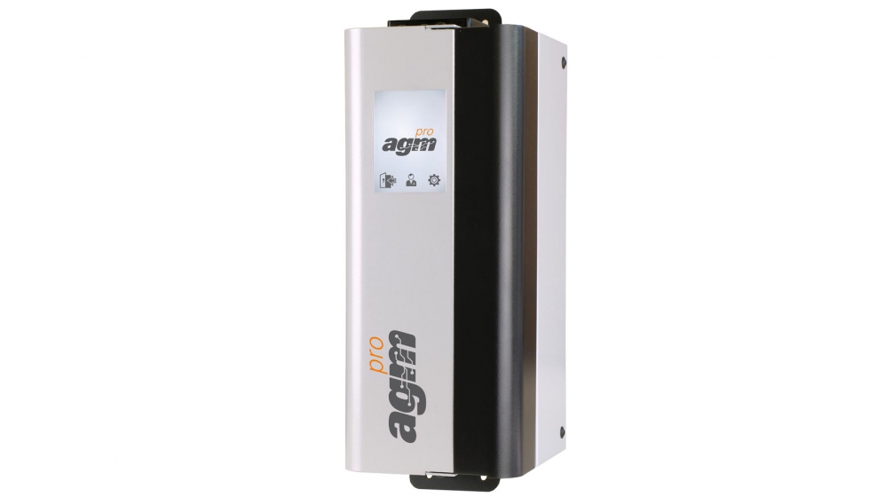


domingo, 19 de marzo de 2017
sábado, 18 de marzo de 2017
compresor de levitación magnética
Las unidades agua-agua con compresor de levitación magnética Turbocor de Sogimair
cuentan con una serie de elementos que les otorgan las elevadas
eficiencias que ofrecen, siendo estos el compresor Turbocor, el
evaporador inundado y el sistema de gestión.
Compresor Turbocor
El
compresor de levitación magnética Turbocor es el corazón de esta
unidad. Es sabido por todos, que los compresores centrífugos presentan
rendimientos muy elevados a cargas plenas, no siendo tan eficientes a
cargas parciales y presentando problemas cuando el sistema de
lubricación falla. El compresor de levitación magnética Turbocor de
Danfoss, elimina estos inconvenientes de los compresores centrífugos, ya
que suprime la presencia de aceite e incrementa el rendimiento de este a
cargas parciales.


Gracias a la tecnología de
levitación, este compresor monta dos cojinetes magnéticos que mantienen
el asta (rotor de compresión) en una posición de levitación, evitando el
rozamiento de esta con los elementos de fricción del compresor, por lo
que se prescinde de la necesidad de la utilización de aceite. Al estar
en ausencia de fricción, se aumenta la vida útil del equipo.
La utilización de un motor DC Brushless y un control Inverter, permite regular la velocidad del asta, con el fin de adecuar el giro a la potencia demandada. Combinando la variabilidad de la velocidad de giro con las dos etapas de compresión del asta, se consiguen altos rendimientos de funcionamiento a cargas parciales.
La utilización de un motor DC Brushless y un control Inverter, permite regular la velocidad del asta, con el fin de adecuar el giro a la potencia demandada. Combinando la variabilidad de la velocidad de giro con las dos etapas de compresión del asta, se consiguen altos rendimientos de funcionamiento a cargas parciales.
La
variación de la velocidad, también permite disminuir el pico de
arranque de la unidad, siendo muy inferior al que dispondríamos con
unidades semejantes equipadas con compresor de tornillo. Este compresor
dispone de un control electrónico que nos permite adecuar en todo
momento la potencia entregad a ala demanda de la instalación,
controlando el posicionamiento del asta con una tolerancia de 7 micras.
Esto lo hace sensible a los fallos de alimentación, pero es por ello que el compresor cuenta con 4 condensadores que carga antes de iniciar su uso, para mantener con tensión suficiente a los elementos de control para conseguir que el asta repose suavemente sobre los cojinetes magnéticos sin dañar el compresor, ante un fallo de suministro.

Esto lo hace sensible a los fallos de alimentación, pero es por ello que el compresor cuenta con 4 condensadores que carga antes de iniciar su uso, para mantener con tensión suficiente a los elementos de control para conseguir que el asta repose suavemente sobre los cojinetes magnéticos sin dañar el compresor, ante un fallo de suministro.

El sistema de gestión de la unidad,
comprueba en todo momento las revolucions por minuto de giro del
compresor, con el fin de adecuar estas a la demanda y evitar problemas
de cavitación o respiración. Al comparar el rendimiento de este
compresor con un compresor de tornillo, podemos apreciar la diferencia
de rendimiento en cargas parciales, siendo estas las de mayor uso según
la definición de cálculo que define el Eseer.
3.2. Evaporador multitubular inundado
Esta
tipología de evaporador, permite disponer de un alto rendimiento,
gracias a la posibilidad de trabajar con temperaturas de evaporación más
altas, hasta un recalentamiento de 1 °C. A diferencia de un evaporador
multitubular estándar, en este caso el refrigerante baña a los tubos por
donde circula el agua.
El empleo de una válvula electrónica y un controlador de nivel, permiten mantener el nivel de líquido en el interior del evaporador adecuado a la demanda de la instalación.


El empleo de una válvula electrónica y un controlador de nivel, permiten mantener el nivel de líquido en el interior del evaporador adecuado a la demanda de la instalación.


3.3. Sistema de control / gestión web
La
centralita de gestión del equipo de producción es la Danfoss MCX. Esta
se suministra con un panel de superficie que permitirá, con un simple
vistazo, visualizar los datos de trabajo, elementos que están en On, o
si ha acontecido alguna alarma. Accediendo al menú de programación,
podremos leer condiciones específicas de trabajo, como presiones de
líquido o gas.
Además, la centralita controla en
todo momento las rpm del compresor de levitación magnética, con lo que
se evitan las posibles cavitaciones o reaspiraciones de refrigerante,
por lo que se tiene bajo control los principales problemas que puede
presentar un compresor centrífugo.
La utilización del control Danfoss MCX y el empleo del compresor de levitación magnética Danfoss Turbocor, otorga a la gama Turboline el certificado emitido por Danfoss Turbocor de alta eficiencia energética.
La utilización del control Danfoss MCX y el empleo del compresor de levitación magnética Danfoss Turbocor, otorga a la gama Turboline el certificado emitido por Danfoss Turbocor de alta eficiencia energética.
La
gama Turbocor presenta una alta eficiencia energética. Esta alta
eficiencia se debe poder medir en cualquier momento, siendo este el
motivo por el que esta unidad incorpora de serie un sistema de gestión
vía web, llamado Web Monitoring, que nos permitirá gestionar el
funcionamiento de la unidad a la vez que obtenemos datos de su
rendimiento.
Este sistema ayudará al equipo de mantenimiento, mostrando el estado de la unidad, pudiendo modificar consignas sin necesidad de desplazarse a la instalación, así como la obtención de gráficos de funcionamiento.
Este sistema ayudará al equipo de mantenimiento, mostrando el estado de la unidad, pudiendo modificar consignas sin necesidad de desplazarse a la instalación, así como la obtención de gráficos de funcionamiento.
La temperatura de masa de un plástico, su importancia y cómo medirla correctamente
La temperatura de masa es una condición de proceso que debería estar
siempre dentro de los márgenes que el fabricante del plástico nos
propone en sus recomendaciones de proceso. Creemos erróneamente en las
fábricas que el valor de regulación de temperatura en el mando de
control de la inyectora, es decir, el valor que le pedimos a las
resistencias eléctricas es el valor de temperatura de la masa. Esto es
un setting de máquina o un input de proceso que controla la temperatura
de la masa pero... solo en parte.
Cuando preguntas en fábricas a qué
temperatura inyectan el material, siempre muestran los valores del mando
de la inyectora. No hay registros de temperatura real de la masa,
¿Confiamos en este input? No deberíamos, pues hay otros factores que
alteran la resultante de la temperatura real de la masa. Los otros
factores determinantes, que influyen más directamente en la temperatura
de masa son:el diseño del husillo, la relación de compresión, las
revoluciones de husillo y la contrapresión a la carga.
La temperatura de masa es un factor determinante del proceso
Una
temperatura demasiado alta puede llegar a degradar el material, aún más
si tenemos un tiempo de permanencia alto. Por el contrario, una
temperatura demasiado baja puede provocar infundidos, fragilidad,
heterogeneidades, exceso de presión necesaria para llenar la cavidad,
etcétera.
Como pudimos ver en el artículo referido al mecanismo del husillo, las resistencias eléctricas en el exterior de la cámara de plastificación, que son las que controlan el mando de la inyectora, generan una capa fundida que permite al husillo girar y hacer la función de “batir” y homogeneizar el material. Por tanto, no creamos que la temperatura de las resistencias que podemos leer en el mando a través de los termopares instalados es la temperatura de la masa a la que estamos inyectando nuestras piezas.
Como pudimos ver en el artículo referido al mecanismo del husillo, las resistencias eléctricas en el exterior de la cámara de plastificación, que son las que controlan el mando de la inyectora, generan una capa fundida que permite al husillo girar y hacer la función de “batir” y homogeneizar el material. Por tanto, no creamos que la temperatura de las resistencias que podemos leer en el mando a través de los termopares instalados es la temperatura de la masa a la que estamos inyectando nuestras piezas.
Entonces,
¿qué alternativa tenemos para conocer la temperatura real de la masa?
Claramente la temperatura real de la masa real solo la podremos obtener
midiendo con una sonda pirométrica la temperatura del material fundido.
Aquí, en esta operación de lectura, se cometen varios errores.
Esta temperatura se suele comprobar en las fábricas haciendo una
eyección de material sobre la bancada de la máquina o sobre un cartón,
etc. Posteriormente se introduce la sonda en la masa fundida y se
observa la lectura. Cuando el valor de la temperatura deja de crecer,
consideramos que es el valor de la temperatura de la masa. Aquí podemos
incurrir en varios errores de lectura:
Si hemos parado la inyectora durante unos minutos, antes de hacer la
eyección para la medición, la medición de temperatura obtenida puede ser
ligeramente mayor que la temperatura real a la que estamos inyectando
el material.
En el caso de que se realicen varias eyecciones previas a la eyección
de la cual tomaremos la temperatura, la lectura obtenida será menor que
la temperatura real puesto que la muestra tomada no es representativa
del material con la máquina a régimen.
Cuando hacemos la eyección,
inmediatamente que el material fundido entra en contacto con el aire y
con la bancada de la inyectora, la temperatura de la masa comienza a
descender rápidamente, esto provoca desfases importantes entre la
lectura realizada y la temperatura real.
Cuando introducimos la sonda en la masa fundida, hay que tener en cuenta el salto térmico que se produce. La sonda estará a la temperatura de la planta de inyección, mientras que la masa fundida estará, por ejemplo a unos 280 grados. Así pues el salto térmico es de más de 250 grados. Dado que el plástico es un mal transmisor térmico, se crea en la sonda inmediatamente una capa fría de material que aislará el material fundido de la lectura de la sonda.
Como ejemplo, si tenemos agua hirviendo a 100 grados y tenemos una sonda pirométrica introducida en nitrógeno líquido (- 195,8 grados C, el salto térmico es similar al que tenemos en una medición de la masa fundida en una inyectora) la lectura que obtendremos es de 0 grados C, debido a este efecto comentado de la capa aislante que se genera alrededor de la sonda.
Cuando introducimos la sonda en la masa fundida, hay que tener en cuenta el salto térmico que se produce. La sonda estará a la temperatura de la planta de inyección, mientras que la masa fundida estará, por ejemplo a unos 280 grados. Así pues el salto térmico es de más de 250 grados. Dado que el plástico es un mal transmisor térmico, se crea en la sonda inmediatamente una capa fría de material que aislará el material fundido de la lectura de la sonda.
Como ejemplo, si tenemos agua hirviendo a 100 grados y tenemos una sonda pirométrica introducida en nitrógeno líquido (- 195,8 grados C, el salto térmico es similar al que tenemos en una medición de la masa fundida en una inyectora) la lectura que obtendremos es de 0 grados C, debido a este efecto comentado de la capa aislante que se genera alrededor de la sonda.
Por
todo lo comentado, tendremos tantas lecturas de temperatura como
personas o técnicos la realicen, esto provoca una falta de confianza en
estas lecturas y lleva a que no sean realizadas sistemáticamente.
Con el fin de unificar el método de lectura y que esta sea homogénea independientemente de la persona que realice la lectura, algunos técnicos americanos desarrollaron un método de lectura de temperatura de masa que intentará homogeneizar las lecturas que se realizan. Este método puede verse en libros y artículos como el método 30/30/30 que “traducido a unidades Europeas seria mas bien el método 20/20/20".
Se trata de:
20 …. Esperar a que la inyectora realice 20 inyectadas o 20 minutos de trabajo continuo.
20 ….. Precalentar la sonda unos 20 grados por encima de la temperatura de lectura esperada.
20 ….. Introducir la sonda en el centro de la masa fundida y esperar unos 20 segundos para tomar la lectura.
Aplicando este método no es necesario remover la sonda durante el tiempo de lectura. Es interesante colocar el extremo de la sonda en el centro de la masa fundida. No es conveniente lecturas en la parte superior de la purga, cerca del aire ambiental, ni cerca del fondo de la purga por el enfriamiento de la capa externa.
También como complemento a este método, es interesante tener a disposición un recipiente donde permanecerá la purga durante la medición.
Con el fin de unificar el método de lectura y que esta sea homogénea independientemente de la persona que realice la lectura, algunos técnicos americanos desarrollaron un método de lectura de temperatura de masa que intentará homogeneizar las lecturas que se realizan. Este método puede verse en libros y artículos como el método 30/30/30 que “traducido a unidades Europeas seria mas bien el método 20/20/20".
Se trata de:
20 …. Esperar a que la inyectora realice 20 inyectadas o 20 minutos de trabajo continuo.
20 ….. Precalentar la sonda unos 20 grados por encima de la temperatura de lectura esperada.
20 ….. Introducir la sonda en el centro de la masa fundida y esperar unos 20 segundos para tomar la lectura.
Aplicando este método no es necesario remover la sonda durante el tiempo de lectura. Es interesante colocar el extremo de la sonda en el centro de la masa fundida. No es conveniente lecturas en la parte superior de la purga, cerca del aire ambiental, ni cerca del fondo de la purga por el enfriamiento de la capa externa.
También como complemento a este método, es interesante tener a disposición un recipiente donde permanecerá la purga durante la medición.
Este recipiente es conveniente que
sea de un material aislante recomendable PTFE por sus excelentes
propiedades térmicas y de antiadherencia.
Una vez realizada la purga, se debe colocar dentro de este recipiente durante la medición. Las características de antiadherencia del PTFE hacen que también sea fácil después de la medición limpiar el recipiente.
Una vez realizada la purga, se debe colocar dentro de este recipiente durante la medición. Las características de antiadherencia del PTFE hacen que también sea fácil después de la medición limpiar el recipiente.
En
el momento en que capturamos la temperatura real a la que estamos
procesando el plástico, tenemos controlado uno de los inputs importantes
del proceso (ver artículo sobre inputs y outputs del proceso de
inyección de plásticos). Esto nos facilitará el control del proceso así
como la investigación ante desviaciones del mismo.
martes, 14 de marzo de 2017
lunes, 13 de marzo de 2017
viernes, 10 de marzo de 2017
lunes, 6 de marzo de 2017
viernes, 3 de marzo de 2017
Suscribirse a:
Entradas (Atom)